Please follow these steps to set up your device:
- Download the Firmware: click on the link below, save and unzip the file.
- Upload the Firmware to the device: Follow the instructions to upload the firmware to your ESP8266 device.
- Connect the device to WiFi: Learn how to connect your device to a WiFi network.
- Connect sensors and Create Panels: Follow the guide to create panels and configure your device.
The demo firmware and a Python uploader are available from the project page. You can flash the board from your computer using the Firmware Uploader page (or any serial uploader of your choice).
Instructions: upload guide (pdf), alternate upload guide.
Click here. to learn how to connect the Firefly to your WiFi local network.
Adding Sensors and Creating Panels on the Firefly
Home Assistant integration over MQTT
Using Firefly alongside Tasmota devices
Instructions to add a 2 channel relay board to the Firefly Mini
Hardware & wiring notes
A few wiring facts worth knowing before you hook up sensors (learned the hard way):
- HC-SR04 ultrasonic sensor: power it from 5 V (the D1 mini VU pin), not 3.3 V, and always divide its Echo output down to ~3.3 V with a resistor divider — the ESP8266 GPIOs are not 5 V tolerant. D0 (GPIO16) cannot be used as the echo pin.
- Active-low outputs: most relay boards energize on LOW. Firefly's
active_lowsetting (default on) means ON always means "energized" in the dashboard, rules and MQTT — the physical pin level is handled for you. - Boot strapping pins: D4 must read HIGH and D8 LOW during reset. Make sure external wiring (like a servo pulling D8 high) can't stop the board from booting.
- Servo outputs: use any GPIO except D0 (no PWM) and A0 (input only). Power the servo from an external 5 V supply with a common ground.
Dashboard, automation and MQTT
Once the board is on your network (or in its own firefly access-point mode), open its address in a browser. From the dashboard you can:
- Create panels: pick an input or output, assign pins, give it a name and unit.
- Calibrate: offset/factor or two-point calibration, plus optional averaging per panel.
- Automate: build IF/THEN rules with conditions on any panel or variable (e.g.
IF tank - time > 1000 THEN relay1 = 1), grouped into programs. - Variables: define your own values and computed values, usable like panels in rules and on the OLED.
- MQTT: publish panel states to any broker, or enable Home Assistant discovery so panels appear automatically as entities.
- Log: record sensor values to a file and download it for analysis.
- Backup / restore everything from the settings page.
Firefly application examples.
Here are some examples of devices you can create with the Firefly development board. This electronic kit allows enthusiasts and professionals to experiment with various applications, from simple projects to more complex systems. With the Firefly, you can develop devices such as light controllers, environmental monitoring systems, and many other innovative projects. Let your creativity run wild and explore everything you can build!
Liquids dispensing system.
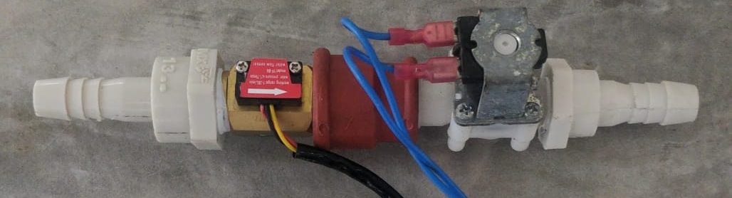
The inspiration for this one came as I over flowed my pool a couple of times so I decided to rig this simple setup. It consists on a solenoid valve to turn on and off the flow of water and a flow sensor that uses a hall effect sensor and outputs negative pulses on each revolution. Both parts are very affordable and easy to get.
The setup is very straight forward.
Hardware connection diagram
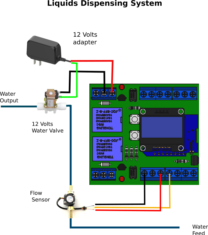
Simple hardware example.
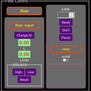
Dispensing Panel
Once you have the hardware ready, go to the Firefly dashboard of your
device and click New Panel. Create two panels: an input
with the flow driver on the pin wired to the sensor's
pulse output (unit L), and a set panel on
the pin driving the valve relay (e.g. D3). Reload the page and both cards
appear.
Calibration uses the input panel's Low / High / Reset buttons: press
Reset (this also zeroes the pulse counter), open the
valve from the valve panel's switch while you fill a container of known
capacity, then close it, press High and enter the
container's capacity. The panel now reads in liters, with a live
liters/min rate beside it.
To dispense automatically, add a program: a rule such as
IF dispensed >= 2 THEN valve = 0 closes the valve at 2
liters, and starting the program with the valve open runs the whole
cycle. This same pattern works for any sensor whose output is pulses
relative to a quantity.
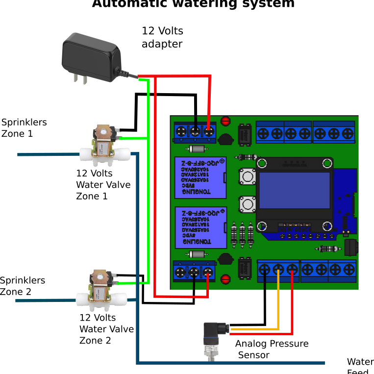
Automatic Watering System
This is a watering system that can be built with very easy
to source components. Normally you wouldn't need a pressure sensor for
such a device as many houses have a constant water supply from the city
water system and in that case the timers are enough for this device but
where I live the municipal water its on for 3 times a week for
like 12 hours each time, most houses have a container at the top that
lasts several days so you always have water in your home. Many houses
have also big cisterns built underground as a backup system.
Many people do their watering the days when you get water
from the city instead of using water from your container up the roof.
Many houses in regions where water is distributed in such a manner have
separate water faucets for the city water to water gardens or do
laundry.
Sorry about the long explanation but was necessary to understand the why of this device as it is connected to the intermittent city water system.
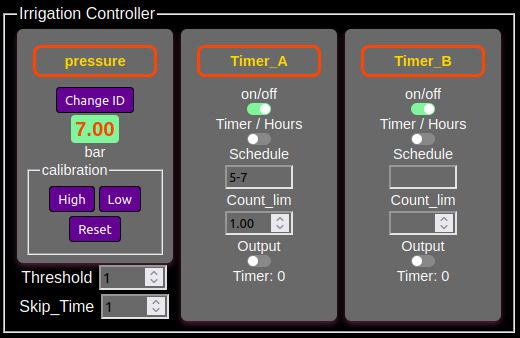
In this case the system has 2 zones, it waits until the pressure reaches a threshold ( to not start the timers until there is good pressure in the system ) and then starts the timer_A for zone 1 and when that is done it starts the timer_B for zone 2, skip_time is the programmable period of time until the next cycle.
Irrigation Panel
Once your hardware is ready, create one timer panel per
zone (D3 and D4 drive the two relays on the Firefly board) plus an
input with the analog driver on A0 for the pressure
sensor.
Timers take a schedule of alternating off/on periods
in seconds, starting from off: 5-10 means 5 seconds off,
10 seconds on. Combinations like 5-10-3-8 run longer
sequences, and the count limit stops the timer after that many full
passes (0 = run forever). For a simple 5-minute watering, use
0-300. Switch a timer to hours mode and you enter clock
times for on and off instead of periods.
To wait for pressure before watering, gate the timers with a rule
instead of starting them by hand, e.g.
IF pressure > 20 THEN zone1 = 1: zone 1 runs when the
mains come up, and a second rule chains zone 2 after it. With 24/7
mains pressure you can skip the sensor and just run the two timers.
Visualization from cloud database.
As an added bonus firefly can upload the data from the pressure
sensor to the cloud database to chart your data and receive alerts when
water is on.

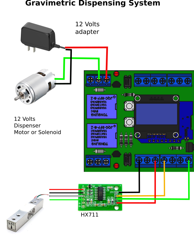
Gravimetric Dispensing System
A gravimetric dispensing system measures and dispenses materials by weight rather than volume. The current firmware has no load-cell driver, so the supported way to build one today is to weigh by proxy: a pressure sensor under the reservoir, an ultrasonic level sensor above it, or a flow sensor on the outlet, calibrated to weight with the two-point calibration below. The dispenser mechanism can be of different kinds: worm screw, conveyor, solenoid valve, etc.
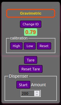
Gravimetric Panel
Weighing works the same way as volume, through any input panel with
two-point calibration. The current firmware has no load-cell driver, so
until one is added the practical route is a sensor the firmware does
support: a pressure sensor under the reservoir, an ultrasonic level
sensor above it, or a flow sensor on the outlet. Calibrate High with a
known weight or level the same way as the dispensing example, and drive
the dispenser mechanism (screw, conveyor, valve) from a set panel with
a rule such as IF dispensed >= target THEN motor = 0.
Tare the container any time with the Low button and 0.